Difference between revisions of "Scenes and Objects"
(Created page with "thumb There are two types of scenes in Visionaire Studio: <span class="inlinecode">Scenes</span> and <span class="inlinecode">Menus</span> (don't g...") |
|||
| Line 1: | Line 1: | ||
| − | [[File:Adding a scene.png|thumb]] | + | [[File:Adding a scene.png|thumb|250px|Add a new scene]] |
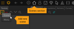
There are two types of scenes in Visionaire Studio: <span class="inlinecode">Scenes</span> and <span class="inlinecode">Menus</span> (don't get confused with the double meaning of the term "scene" here). When adding a new scene via the <span class="inlinecode">[+]</span> icon, you can choose between the two types (see image). Scene type scenes are the stages of your game. Your characters walk through them, and the user can interact with objects you placed on them. It's basically what your world is made up of. Menu type scenes are almost the same, but without the characters, so to speak. They also have some special features used for menu screens. | There are two types of scenes in Visionaire Studio: <span class="inlinecode">Scenes</span> and <span class="inlinecode">Menus</span> (don't get confused with the double meaning of the term "scene" here). When adding a new scene via the <span class="inlinecode">[+]</span> icon, you can choose between the two types (see image). Scene type scenes are the stages of your game. Your characters walk through them, and the user can interact with objects you placed on them. It's basically what your world is made up of. Menu type scenes are almost the same, but without the characters, so to speak. They also have some special features used for menu screens. | ||
| Line 7: | Line 7: | ||
== Scene properties == | == Scene properties == | ||
| − | [[File:Scene settings.png|thumb]] | + | [[File:Scene settings.png|thumb|200px|Scene settings]] |
Open the scene properties window via the small cog icon next to the "Objects" tab (see image). | Open the scene properties window via the small cog icon next to the "Objects" tab (see image). | ||
| Line 24: | Line 24: | ||
== The scene viewport == | == The scene viewport == | ||
| − | [[File:Scene viewport navigation.png|thumb]] | + | [[File:Scene viewport navigation.png|thumb|150px]] |
As soon as you have linked a background image in the scene properties, it will show up in the viewport. Here you will place images and animations, define positions and draw areas and paths. You can zoom, scroll and drag the scene while working on it. Dragging is important, because it lets you draw and place things even outside of the visible scene. You will need this, if you want a character to leave the scene by walking past the edge of the screen, for example. | As soon as you have linked a background image in the scene properties, it will show up in the viewport. Here you will place images and animations, define positions and draw areas and paths. You can zoom, scroll and drag the scene while working on it. Dragging is important, because it lets you draw and place things even outside of the visible scene. You will need this, if you want a character to leave the scene by walking past the edge of the screen, for example. | ||
* '''Drag''' the scene while holding the middle mouse button; alternatively use the left mouse button while holding "Ctrl" (PC) or "Cmd/⌘" (Apple) | * '''Drag''' the scene while holding the middle mouse button; alternatively use the left mouse button while holding "Ctrl" (PC) or "Cmd/⌘" (Apple) | ||
| Line 35: | Line 35: | ||
== Way systems == | == Way systems == | ||
| − | [[File:Impossible routes.png|thumb|This doesn't work without way points]] | + | [[File:Impossible routes.png|thumb|250px|This doesn't work without way points]] |
Before we can put characters on the scene, we need to tell them which areas are walkable. Actually they don't even know where the floor is, because we're working with a 2D engine and have to "fake" the third dimension. Scenes are usually drawn perspectively to give the impression of 3D space. But even if you're planning to create a 2D side-scroller, you need to define '''way borders'''. | Before we can put characters on the scene, we need to tell them which areas are walkable. Actually they don't even know where the floor is, because we're working with a 2D engine and have to "fake" the third dimension. Scenes are usually drawn perspectively to give the impression of 3D space. But even if you're planning to create a 2D side-scroller, you need to define '''way borders'''. | ||
| Line 45: | Line 45: | ||
=== Way borders === | === Way borders === | ||
| − | [[File:Way borders.png|thumb|Way borders]] | + | [[File:Way borders.png|thumb|250px|Way borders]] |
| − | [[File:Way border editing.png|thumb]] | + | [[File:Way border editing.png|thumb|150px]] |
The way border is a closed polygon made up of points connected by straight lines. You can draw multiple polygons next to each other into one scene, if you have characters moving independently from each other in different areas, for example. But in most cases a single way border area will do, because a character can't walk from one polygon to the other unless he gets teleported. | The way border is a closed polygon made up of points connected by straight lines. You can draw multiple polygons next to each other into one scene, if you have characters moving independently from each other in different areas, for example. But in most cases a single way border area will do, because a character can't walk from one polygon to the other unless he gets teleported. | ||
| Line 68: | Line 68: | ||
=== Way points === | === Way points === | ||
| − | [[File:Pathfinding.png|thumb|Characters' pathfinding]] | + | [[File:Pathfinding.png|thumb|250px|Characters' pathfinding]] |
| − | [[File:Way points.png|thumb|Way points]] | + | [[File:Way points.png|thumb|250px|Way points]] |
| − | [[File:Way points editing.png|thumb]] | + | [[File:Way points editing.png|thumb|150px]] |
| + | |||
==== Pathfinding ==== | ==== Pathfinding ==== | ||
| Line 81: | Line 82: | ||
* '''Add a new point''' with the left mouse button; the new point will automatically get connected to the previously selected way point | * '''Add a new point''' with the left mouse button; the new point will automatically get connected to the previously selected way point | ||
* '''Select a point''' with the left mouse button | * '''Select a point''' with the left mouse button | ||
| − | * '''Connect/disconnect two existing points''' by selecting one | + | * '''Connect/disconnect two existing points''' by selecting one of them and clicking on the other point with the right mouse button |
* '''Deselect a point''' by clicking somewhere else with the right mouse button | * '''Deselect a point''' by clicking somewhere else with the right mouse button | ||
* '''Move a point''' with the left mouse button, or select it and use the arrow keys | * '''Move a point''' with the left mouse button, or select it and use the arrow keys | ||
| Line 90: | Line 91: | ||
==== Character scaling ==== | ==== Character scaling ==== | ||
| − | [[File:Character scaling.png|thumb|Character scaling]] | + | [[File:Character scaling.png|thumb|250px|Character scaling]] |
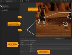
Besides pathfinding, way points have a second important meaning. Each way point holds a character scaling information. Since we are "faking" the third dimension, we have to create the illusion of perspective by reducing the size of the character when he walks to the "back" of the scene (which is upwards in 2D). | Besides pathfinding, way points have a second important meaning. Each way point holds a character scaling information. Since we are "faking" the third dimension, we have to create the illusion of perspective by reducing the size of the character when he walks to the "back" of the scene (which is upwards in 2D). | ||
By default, every way point is set to a scaling of -1 (means: not set). Numbers from 0 to 200 are interpreted as percentage values. If you have two points with different values (usually a bigger number at the bottom of the scene, a smaller number further upwards), the engine will scale the character at the position of the respective way points according to these values and interpolate the character size in the rest of the scene. | By default, every way point is set to a scaling of -1 (means: not set). Numbers from 0 to 200 are interpreted as percentage values. If you have two points with different values (usually a bigger number at the bottom of the scene, a smaller number further upwards), the engine will scale the character at the position of the respective way points according to these values and interpolate the character size in the rest of the scene. | ||
| − | Adding a scale factor to too many points can lead to unexpected results. Two settings – one for the front, one for the back – will do for most scenes. If the scaling gradient only runs vertically (which again is usually the case), it is good practice to add way points especially for scaling purposes outside of the scene | + | Adding a scale factor to too many points can lead to unexpected results. Two settings – one for the front, one for the back – will do for most scenes. If the scaling gradient only runs vertically (which again is usually the case), it is good practice to add way points especially for scaling purposes outside of the scene where they are easily to maintain (see the image). This is an exception from the rule to have all way points connected and inside the way border. |
| − | When editing way points, the <span class="inlinecode">Character size</span> of the selected point can be set in the "Character size" tab below the viewport. You can also select the animation sprite of a <span class="inlinecode">Character for preview</span> there | + | When editing way points, the <span class="inlinecode">Character size</span> (scale factor) of the selected point can be set in the "Character size" tab below the viewport. You can also select the animation sprite of a <span class="inlinecode">Character for preview</span> there which will get displayed at the cursor when hovering over the viewport. Instead of typing the scale factor in, you may change it by using the scroll wheel. The preview sprite will instantly adapt, making it easy to find the right size. |
== Action areas == | == Action areas == | ||
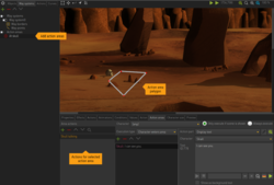
| − | [[File:Action area.png|thumb|Action area]] | + | [[File:Action area.png|thumb|250px|Action area]] |
Action areas are areas on a scene which trigger an action when a character enters or leaves them. The respective action area doesn't have to be the character's destination, he just needs to cross it. He won't stop walking either (unless you tell him to stop in the triggered action). Both the playable character and non-playable characters can trigger actions. | Action areas are areas on a scene which trigger an action when a character enters or leaves them. The respective action area doesn't have to be the character's destination, he just needs to cross it. He won't stop walking either (unless you tell him to stop in the triggered action). Both the playable character and non-playable characters can trigger actions. | ||
| − | You find action areas on the "Way systems" tab below the way systems. Add as many areas as you like. With an action area selected, you can draw a polygon in the viewport | + | You find action areas on the "Way systems" tab below the way systems. Add as many areas as you like. With an action area selected, you can draw a polygon in the viewport (just like drawing way borders). Add actions to the action area with an <span class="inlinecode">Execution type</span> of either "Character enters area" or "Character leaves area". Select which <span class="inlinecode">Character</span> should trigger the action, "[any]" being the default. Only change the <span class="inlinecode">"Only execute if scene is shown"</span> option to <span class="inlinecode">"Always execute"</span>, if it's really necessary, as it means more stress for the engine. |
| Line 120: | Line 121: | ||
== Lightmaps == | == Lightmaps == | ||
| − | [[File:Lightmap.png|thumb| | + | [[File:Lightmap.png|thumb|350px|Impact of lightmap on character]] |
Lightmaps are image files that add a color tint to the characters in the scene. See them as some kind of overlay, which itself is not visible, but only affects the characters to simulate different lightings in the scene. For example: if your scene is partly shadowed and partly sunlit, characters walking through it should adapt to the lighting situation. The initial lightmap of a scene is defined in the [[#Scene_properties|scene properties]]; you may change it during the game through an [[Action Parts#Set_lightmap|action part]]. | Lightmaps are image files that add a color tint to the characters in the scene. See them as some kind of overlay, which itself is not visible, but only affects the characters to simulate different lightings in the scene. For example: if your scene is partly shadowed and partly sunlit, characters walking through it should adapt to the lighting situation. The initial lightmap of a scene is defined in the [[#Scene_properties|scene properties]]; you may change it during the game through an [[Action Parts#Set_lightmap|action part]]. | ||
Revision as of 10:17, 13 October 2022
There are two types of scenes in Visionaire Studio: Scenes and Menus (don't get confused with the double meaning of the term "scene" here). When adding a new scene via the [+] icon, you can choose between the two types (see image). Scene type scenes are the stages of your game. Your characters walk through them, and the user can interact with objects you placed on them. It's basically what your world is made up of. Menu type scenes are almost the same, but without the characters, so to speak. They also have some special features used for menu screens.
While this page handles scene type scenes, there is a separate page for menus. Many things explained here apply to menus as well though.
Scene properties
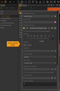
Open the scene properties window via the small cog icon next to the "Objects" tab (see image).
- Background image: Set the background image for the scene. If it's larger than the game's resolution, the scene becomes scrollable.
- Scene name: Entering a scene name is optional. This name will only show up in savegame timestamps. Leave this field empty, if you don't want that.
- Background music: Specify a sound file to play in the background. You may also adjust its Volume and Balance. If you add the same background music to different scenes and change between those scenes in the game, the track will play continuously. Check the "Continue music from the previous scene" option to continue playing the track used in the previous scene instead of setting a sepecific sound file for this scene. The music then depends on which scene you showed before. There are action parts for changing and adjusting the background music during the game.
- Lightmap: Specify an image file that serves as a lightmap.
- Particle system: Select a particle system to show in the scene.
- Way system: Select the initial way system for the scene.
- Savegame screenshot: Set an image file that serves as the screenshot thumbnail for this scene when playing on mobile devices (taking in-game screenshots is not possible on mobile devices).
- Scroll scene if the cursor is at the screen edge: By default, scenes wider or higher than the game's resolution will scroll automatically, keeping the playable character in sight. If you check this option, the scene scrolling is triggered when the mouse cursor approaches the screen edges.
- Test character: tbd
- Audio containers: Add audio containers with sounds you want to use in this scene. If you make use of this audio system feature, you might do without the "Background music" setting.
The scene viewport
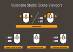
As soon as you have linked a background image in the scene properties, it will show up in the viewport. Here you will place images and animations, define positions and draw areas and paths. You can zoom, scroll and drag the scene while working on it. Dragging is important, because it lets you draw and place things even outside of the visible scene. You will need this, if you want a character to leave the scene by walking past the edge of the screen, for example.
- Drag the scene while holding the middle mouse button; alternatively use the left mouse button while holding "Ctrl" (PC) or "Cmd/⌘" (Apple)
- Zoom in & out of the scene with the mouse wheel while holding "Ctrl" (PC) or "Cmd/⌘" (Apple), or use the magnifying tools above the viewport
- Scroll vertically with the mouse wheel
- Scroll horizontally with the mouse wheel while holding "Alt" (PC) or "Opt/⌥" (Apple)
Way systems
Before we can put characters on the scene, we need to tell them which areas are walkable. Actually they don't even know where the floor is, because we're working with a 2D engine and have to "fake" the third dimension. Scenes are usually drawn perspectively to give the impression of 3D space. But even if you're planning to create a 2D side-scroller, you need to define way borders.
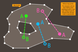
Characters are only able to walk inside these way border polygons; they can't leave them. When the user clicks somewhere, the current character will walk to that point, taking the shortest possible route: a straight line. But he will only do so, if he can reach his destination on that shortest route. The image shows situations where it is not possible to walk directly from point A to point B because of the shape of the way border polygon – or because of the user clicking outside the way borders. Taking the straight route would make the character leave the walkable area, and since this is not allowed, he won't start walking at all. That's why we also have to define way points – a network of paths the character can follow.
Together, way border polygons and the way point network make up a way system. You can add as many way systems to your scene as you like on the "Way systems" tab. One is mandatory (if you have moving characters), and only one way system per scene can be active at a time. The initially active way system is defined in the scene properties; you can change it anytime via the "Change way system" action part. Use this to block/open certain areas of the scene for the character in the course of the game.
Way borders
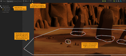
The way border is a closed polygon made up of points connected by straight lines. You can draw multiple polygons next to each other into one scene, if you have characters moving independently from each other in different areas, for example. But in most cases a single way border area will do, because a character can't walk from one polygon to the other unless he gets teleported.
If you have obstacles within the walkable area (like the rocks and the skull in the example image), you have to "cut holes" into the polygon, otherwise the character would run through them. To make him really walk behind the obstacles, you'll also need to add cropped images of the rocks. This is done with objects.
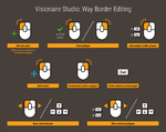
If you select the "Way borders" entry of your way system in the list left to the viewport, you may draw the way borders:
- Add a new point with the left mouse button, points will be connected automatically; if you click on the line of an existing polygon, a new point will be added to that line
- Close a polygon by setting the last point onto the first one or – more convenient – by clicking the right mouse button
- Start adding a new polygon inside an existing polygon (to cut holes) with the left mouse button while holding "Alt" (PC) or "Opt/⌥" (Apple)
- Select a point by clicking on it with the left mouse button
- Deselect a point by clicking somewhere else with the right mouse button; this will select the whole polygon
- Delete the selected point or polygon by pressing the "Delete" key
- Move a point with the left mouse button, or select it and use the arrow keys
- Move the polygon with the left mouse button while holding "Ctrl" (PC) or "Cmd/⌘" (Apple), or use the arrow keys; multiple polygons will all move together
Make sure not to draw the way borders too close to walls, obstacles etc. The engine will only keep the animation center (usually between the character's feet) inside the polygon and doesn't care about the dimensions of the animation sprites. So if the distance is too small, parts of the character might end up "inside" a wall.
Way points
Pathfinding
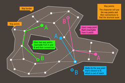
Way points are added in a network structure, meaning that every way point connects to one or more other way points. The engine utilizes this network to find the shortest route from A to B. Think of it as a highway system with the way points being junctions and exits. If the destination point B is not reachable for the character from point A, the engine sends him to one of the way points. If the destination is still out of sight, the character will follow the connections until he gets to a point from where he can walk directly to point B. If the destination point lies outside the way border (because the user clicked there), the way point that is closest to that destination becomes the new destination. See the image for some examples.
Planning the layout of way points often needs a bit of trial and error. Try not to overcomplicate the network; start with fewer points. Make sure that all way points are connected. Gaps may lead to strange walking behaviour. Place way points only inside the way border.
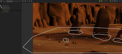
If you select the "Way points" entry of your way system in the list left to the viewport, you may draw the way points:
- Add a new point with the left mouse button; the new point will automatically get connected to the previously selected way point
- Select a point with the left mouse button
- Connect/disconnect two existing points by selecting one of them and clicking on the other point with the right mouse button
- Deselect a point by clicking somewhere else with the right mouse button
- Move a point with the left mouse button, or select it and use the arrow keys
- Delete the selected point by pressing the "Delete" key
Character scaling
Besides pathfinding, way points have a second important meaning. Each way point holds a character scaling information. Since we are "faking" the third dimension, we have to create the illusion of perspective by reducing the size of the character when he walks to the "back" of the scene (which is upwards in 2D).
By default, every way point is set to a scaling of -1 (means: not set). Numbers from 0 to 200 are interpreted as percentage values. If you have two points with different values (usually a bigger number at the bottom of the scene, a smaller number further upwards), the engine will scale the character at the position of the respective way points according to these values and interpolate the character size in the rest of the scene.
Adding a scale factor to too many points can lead to unexpected results. Two settings – one for the front, one for the back – will do for most scenes. If the scaling gradient only runs vertically (which again is usually the case), it is good practice to add way points especially for scaling purposes outside of the scene where they are easily to maintain (see the image). This is an exception from the rule to have all way points connected and inside the way border.
When editing way points, the Character size (scale factor) of the selected point can be set in the "Character size" tab below the viewport. You can also select the animation sprite of a Character for preview there which will get displayed at the cursor when hovering over the viewport. Instead of typing the scale factor in, you may change it by using the scroll wheel. The preview sprite will instantly adapt, making it easy to find the right size.
Action areas
Action areas are areas on a scene which trigger an action when a character enters or leaves them. The respective action area doesn't have to be the character's destination, he just needs to cross it. He won't stop walking either (unless you tell him to stop in the triggered action). Both the playable character and non-playable characters can trigger actions.
You find action areas on the "Way systems" tab below the way systems. Add as many areas as you like. With an action area selected, you can draw a polygon in the viewport (just like drawing way borders). Add actions to the action area with an Execution type of either "Character enters area" or "Character leaves area". Select which Character should trigger the action, "[any]" being the default. Only change the "Only execute if scene is shown" option to "Always execute", if it's really necessary, as it means more stress for the engine.
Objects
tbd
Components
tbd
Lightmaps
Lightmaps are image files that add a color tint to the characters in the scene. See them as some kind of overlay, which itself is not visible, but only affects the characters to simulate different lightings in the scene. For example: if your scene is partly shadowed and partly sunlit, characters walking through it should adapt to the lighting situation. The initial lightmap of a scene is defined in the scene properties; you may change it during the game through an action part.
Calling a lightmap an overlay may be somewhat misleading. The whole character gets tinted in one color only; namely the color of the particular lightmap pixel that corresponds to the current position of the character's animation center (see image). White areas in the lightmap do not change the character's color.
Lightmaps don't have to be created at full game resolution. They will automatically be scaled to fit the size of the scene. If your scene is 1920 x 1080 pixels, a lightmap of 960 x 540 pixels (or even smaller) will probably do.
